- Seismograph : Signal enhancement type fully digital 24 channel seismograph
- Geophones : Borehole 3D Geophone
- Cable : Geophone spread cables, 1m spacing, and water proof joints
- Hammer : Seismic hammer
- Software : Geotom CG
Welcome to Drisana Geotechnical Consultancy!
Equipments and Accessories


Energy Source:
Specially designed for small-scale cross-hole surveys, this compact hammer can be used to generate both P and S waves. The hammer can be downloaded using the steel cable and clamped to the requested depth by a pneumatic clamping system manually controlled by a lever from the surface; simply pushing up the steel cable to execute the first shot, the trigger installed on the energizer will start the acquisition for the “P/S”. After that you will have to drop the mass to make the acquisition with inverse polarity.
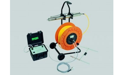
Borehole 3D Geophones:
The DHTG borehole geophone has been designed to meet the most demanding Customers request. The system (consisting in a probe, a control unit, the cable together with a cable reel, and a cable clamp) is as a matter of fact characterized by the possibility to get a reliable adhesion to borehole walls, obtained by a progressive flexure of a harmonic steel spring placed parallely to the probe. Three 10 Hz geophones, oriented according to the x-y-z axis, are housed inside the probe for the determination of the time of arrival of the type’s’ and type 'p' seismic waves.
Seismograph:
PASI model 16S24-U Engineering Seismograph shall be used to record field data. The seismograph has the signal enhancement or stacking capability. The seismograph records the arrival of seismic waves through 24 channels. The seismic waves detected by each geophone are to be displayed simultaneously on the screen.
CROSS HOLE SEISMIC:
The Crosshole Seismic Test makes direct measurements of compression velocities and shear wave velocities, in boreholes advanced through soil or rock. At selected depths down the borehole, a borehole seismic source is used to generate a seismic wave train. Two downhole receivers (3d Geophone) are used to detect the arrival of the seismic wave train in offset borings.
Cased borings that are spaced 0.5m to 5m apart are typically used. The distance between boreholes at the test depths is measured using a borehole deviation survey. The borehole Seismic source is connected to and triggers a data recording system that records the response of the downhole receiver(s), thus measuring the travel time of the wave train between the source and receiver(s). The compression or shear wave velocity is calculated from the measured distance and travel time for the respective wave train.


Interpretation and data Processing:
Traveltimes shall be processed to calculate velocities, or amplitudes processed to calculate attenuation coefficients. Sources and receivers shall be in any configuration within a 3-D grid. Anisotropy shall be specified for each point of the grid. Options for constraining the inversion to improve the reliability of results include:
- Maximum and minimum calculated velocities.
- Constant velocity in user-selected areas or volumes in the grid.
- Groups of nodes with similar velocities, such as horizontal layers or vertical columns.
- Constraints that take into account the uncertainty in site knowledge.
- Adjustable damping and smoothing to reduce small-scale variations in calculated velocity./li>
CALCULATION OF SOIL PARAMETERS:
The dynamic soil parameters are calculated from seismic wave and the bulk density of the corresponding of the subsurface strata.
- The Poisson’s Ratio is determined directly from the compression (P) wave and shear (S) wave data. It is expressed by the ratio of transverse strain to longitudinal strain. Its dynamic determination is expressed as: σ = (m2-2)/[2*(m2-1)] where m= VP / Vs
- Young’s Modulus E is the uni-axial stress-strain ratio. Its dynamic value is expressed by the following equation: E = ρ VP2 (1+σ) (1-2σ)/(1-σ)
- The shear Modulus G is the stress-strain ratio for simple shear. Its dynamic value is obtained by the following: G = E/2 (1+ σ) = ρ V 2
- The Bulk Modulus is calculated as follows: K = E / (3 - 6σ)
Where ρ is mass density in kN. s2/m4, σ is Poisson’s ratio and VP are P-wave velocity in m/sec, E, G & K are in kN/m2. The test results are presented afterwards in a tabular form.
PICKING OF FIRST ARRIVALS
The picking was done manually to see arrival of P and S waves on the respective Geophones. The time of travel from Source to Receiver hole is used to determine the velocities of P & Shear waves, as distance between the boreholes is known.
VELOCITY CALCULATIONS
Velocity calculation was done using the time derives as above and the distance between the two Receiver holes from the Source hole.
Final Profile

Photograph:

